Validation structure: Nibelungen Bridge Worms
The methods developed for model generation, digital linkage and derivation of condition indicators shall be tested and validated on a demonstrator structure. For this purpose, the Nibelungen Bridge Worms was selected as the validation structure.
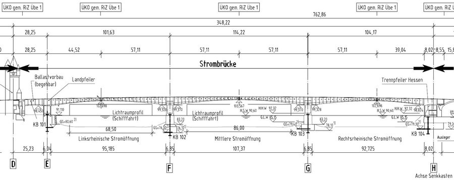
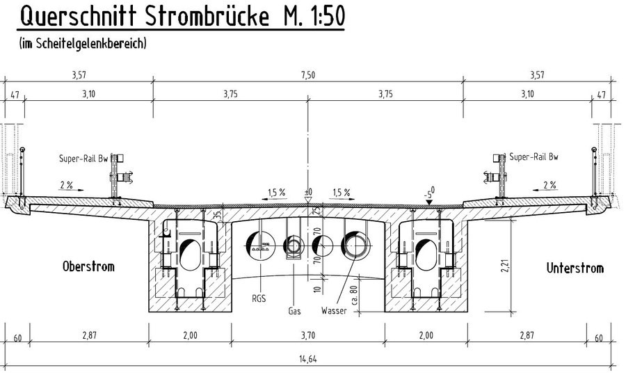
The Nibelungen Bridge Worms connects the Rhineland-Pfalz city of Worms across the Rhine with the Hessian cities of Lampertheim and Bürstadt. The river bridge has a span configuration of approx. 101.65 m - 114.20 m - 104.20 m (Figure 1). The spans are each composed of two cantilever beams. They are constrained in the piers and connected in the middle by vertically braced Gerber joints. In addition, there is a short span of approx. 23.25 m in front of the bridge tower on the Worms side, which serves as the counterweight for the superstructure cantilevered on the other side of the land pier. On the Hessian side, due to a lack of sufficient space for a counterweight, the suspension had to be achieved via vertical tendons anchored to the newly installed cantilever beams of the abutment foundation (Figure 1). The superstructure cross-section has a deck slab width of 14.00 m between the outer edges of the parapets. It is designed as a double-webbed girder. The webs are in the form of haunched box girders and have a width of 2.00 m each (Figure 2). The height of these haunched beams varies between 6.50 m at the top of the piers and 2.50 m in the joint area. With a constant web thickness of 35 cm, and 50 cm in the short span in front of the bridge tower, clear widths inside the box girders of 1.30 to 1.00 m can be maintained.
For the development and validation of the methods, the subprojects will be provided with various data of this structure in different processing stages (raw data and processed data).
From the coordination project, a point cloud from a laser scan and the photos from a photogrammetric survey are provided as raw data for a substructure. From the photos, a three-dimensional geometric reconstruction of the recorded object is created and also made available (relative accuracy of +- 5 mm, point density min. every 2 cm one point). From both data sources, a 3D CAD model of the visible construction elements is generated, which can be used as a basis for developments in the subprojects (.dfx or .dwg format).
In addition, all available as-built documents (plans, recalculation, test report of the main test, etc.) will be provided. It is also planned to carry out additional non-destructive examinations for the priority program and to make these data available centrally. These include, for example, radar surveys to verify tendon location, concrete cover measurements, concrete strength surveys, carbonation depth measurements, and chloride penetration depth measurements. These measurements will be concentrated in one marginal field and supplemented by spot measurements in the other fields.
In the first funding period of the SPP, initial monitoring will be installed at the structure from central funds, which will be supplemented in the second funding period according to the recommendations of the subprojects. Initially, about 20 measuring points will be provided at relevant points, these are displacement measurements (e.g. at roadway crossings), strain measurements, inclination measurements and acceleration measurements. The data will be recorded at a measurement frequency of 200 Hz. Climatic data (temperature and humidity) are recorded at intervals of 10 minutes. The central measuring system will be designed in such a way that, if necessary, the subprojects can add their own measuring points and also record, transmit and store this measurement data. The transmission, external storage and access to the data will be ensured by the coordination project.